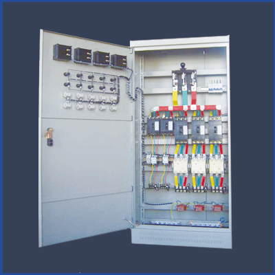
動力配電中心(以下簡稱
Power distribution center (hereinafter referred to as
柜內(nèi)分割成四個(gè)隔室:
The cabinet is divided into four compartments:
水平母線隔室:在柜的后部�;功能單元隔室:在柜前上部或柜前左邊;
Horizontal busbar compartment: at the rear of the cabinet; Functional unit compartment: located on the upper or left side of the cabinet front;
電纜隔室:在柜前下部或柜前右邊����;控制回路隔室:在柜前上部;
Cable compartment: located in the lower part or right side of the cabinet front; Control circuit compartment: located in the upper front of the cabinet;
分隔措施:水平母線隔室與功能單元隔室����、電纜隔室之間采用三聚氰胺酚醛平心板或鋼板分隔。
Separation measures: The horizontal busbar compartment is separated from the functional unit compartment and cable compartment using melamine phenolic flat core plates or steel plates.
控制回路隔室與功能單元隔室之間用阻燃型聚胺脂發(fā)泡塑料模制罩殼分隔�。
The control circuit compartment and the functional unit compartment are separated by a flame-retardant polyurethane foam plastic molded cover.
左邊的功能單元隔室與右邊的電纜隔室之間用鋼板分隔。
The functional unit compartment on the left is separated from the cable compartment on the right by steel plates.
抽出式電動控制中心和小電流的動力配電中心(以下簡稱為抽出式
Drawout electric control center and small current power distribution center (hereinafter referred to as drawout type)

抽出式MCC柜內(nèi)分成三個(gè)隔室����,即柜后部的水平母線隔室��,柜前部左邊的功能單元隔室�����,柜前部右邊的電纜隔室��。水平母線隔室與功能單元隔室之間用阻燃型發(fā)泡塑料制成的功能板分隔����,電纜隔室與水平母線隔室���、功能單元隔室之間用鋼板分隔���。
The withdrawable MCC cabinet is divided into three compartments, namely the horizontal busbar compartment at the rear of the cabinet, the functional unit compartment on the left front of the cabinet, and the cable compartment on the right front of the cabinet. The horizontal busbar compartment and functional unit compartment are separated by functional boards made of flame-retardant foam plastic, and the cable compartment is separated from the horizontal busbar compartment and functional unit compartment by steel plates.
可移式電動機(jī)控制中心和小電流動力配電中心(以下可簡稱為可移式
Portable motor control center and small current power distribution center (hereinafter referred to as portable)
可移式MCC的框體結(jié)構(gòu)特征同2.1和2.2。
The frame structure characteristics of the movable MCC are the same as those in 2.1 and 2.2.
功能單元設(shè)計(jì)成可移式結(jié)構(gòu)���,功能單元與垂直母線的連接�����,采用一次隔離觸頭�,即使與其連接的電路是帶電的,也可以從設(shè)備中完整地取出和放回該功能單元���,另一端為固定式結(jié)構(gòu)�。
The functional unit is designed as a movable structure, and the connection between the functional unit and the vertical busbar adopts a primary isolation contact. Even if the circuit connected to it is live, the functional unit can be completely removed and placed back from the equipment, and the other end is a fixed structure.
可移式MCC的功能單元分為8E/4����,8E/2�,8E,16E���,24E���,32E和40E。功能單元隔室總高度也是72E����。
The functional units of portable MCC are divided into 8E/4, 8E/2, 8E, 16E, 24E, 32E, and 40E. The total height of the functional unit compartment is also 72E.
母線系統(tǒng)
Bus system
水平母線安裝于柜后獨(dú)立的母線隔室中,它有二個(gè)可選擇的安裝位置�,即柜高的三分之一或三分之二處,母線可按需要裝于上部或下部�����,也可以上下二組同時(shí)安裝,二組母線可以單獨(dú)使用����,也可以并聯(lián)使用。每相母線由2根或8根母線并聯(lián)���,母排截面有10×32×2�����,10×60×2��,10×80×2�,10×60×4��,10×80×2×2和10×60×4×2 六種��。
The horizontal busbar is installed in an independent busbar compartment behind the cabinet, with two optional installation positions, namely one-third or two-thirds of the cabinet height. The busbar can be installed on the upper or lower part as needed, or two sets of upper and lower buses can be installed simultaneously. The two sets of busbars can be used separately or in parallel. Each phase of the busbar is connected in parallel with 2 or 8 busbars, with a busbar cross-section of 10 × thirty-two × 2����,10 × sixty × 2,10 × eighty × 2��,10 × sixty × 4�,10 × eighty × two × 2 and 10 × sixty × four × Two or six types.
垂直母線
Vertical busbar
垂直母線50×30×5的"L"型銅母線�,它被嵌裝于用阻燃型塑料制造的功能板中��。帶電部分的防護(hù)達(dá)IP20�。
Vertical busbar 50 × thirty × The "L" type copper busbar of 5 is embedded in a functional board made of flame-retardant plastic. The protection of live parts reaches IP20.
中性母線(N線)和中性保護(hù)母線(PE線或PEN線)中性母線和中性保護(hù)母線平行地安裝在功能單元隔室的下部和垂直安裝在電纜室中,N線與PE線之間如用絕緣子相隔���,則N線與PE線分別使用����,二者之間如用導(dǎo)體連接�,即成PEN線�。
The neutral busbar (N line) and neutral protection busbar (PE line or PEN line) are installed parallel to the lower part of the functional unit compartment and vertically in the cable compartment. If insulators are used to separate the N line and PE line, they are used separately. If conductors are used to connect the two, they become PEN lines.
